Image Info
- Dimensions: 560 × 1024 pixels
Gallery

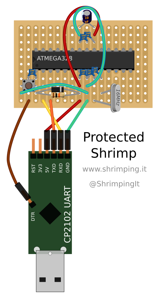
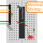
- Erratum: this circuit should show a diode connecting from the reset pin to the power pin, in parallel with the 10KiloOhmresistor. The diode is there to handle a very rare failure condition and can normally be omitted.
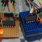

Please note that the diagram above, based on Fritzing’s approach to rendering stripboard, are fundamentally misleading. The image suggests that the copper is on the same side as the components, but rather, through-hole soldering requires the component to be inserted through the side without the copper, and it is then retained by soldering it in place on the other side. Additionally, a cut is required to divide each copper rail into two at the rear, beneath the chip, to make it equivalent to a breadboard (which has two sets of rows isolated by a divider down the middle). This is by no means obvious and should be fixed by producing a proper build sequence for the soldered circuit too. The image at http://shrimping.it/blog/shrimp/stripboard_vs_breadboard_alternative/ gives you some idea of the orientation of the board, and the equivalence of breadboard and properly cut stripboard.