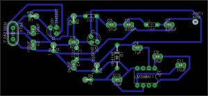
PCB radio design. Credit: Flickr user MStyne
As @ShrimpingIt gets wider appeal, offers from those out there who want to help us put the #Shrimp on PCB are getting to be once or twice weekly!
First of all, thanks. The engagement from our global audience is always welcome.
We’re deeply aware that most of the knowledge and insights are out there, and don’t originate with us. Indeed this is the main purpose of the project in the first place – to convert the community’s visions and approaches into a form which is digestible by hobbyists and educators who are just starting out.
However, in summary, the reason we’re not shipping PCBs; in our view they are not digestible and arguably no good for those learning prototyping and physical computing, or those learning to teach the subjects. This is especially true of manufactured, multi-layer PCBs.
We know PCBs are cheap, that PCB=industrialisation and that it’s possible to make them at home with just a few chemicals, or have them fabricated and shipped cheaply, even in small volumes. It’s important for educators to realise that these activities are substantially harder and have higher thresholds of adoption than breadboarding or stripboarding. However, the main issue is elsewhere.
On this page, I hope to explain some of the conceptual and structural issues between projects on PCB and those on breadboard or stripboard. If I’ve redirected you here after a friendly email exchange, please don’t be offended. This isn’t the end of the debate. It just saves me sending a stock email, and provides a public context for discussing the issue.
We want people to reflect on why a PCB would be a good idea, beyond the instinct that it’s somehow progress to go from breadboard to PCB. It may be progress for you, but is it progress for those receiving the PCBs, especially people learning prototyping?
PCBs are Inflexible
A PCB is more like the end of the design process than the beginning. We think it’s important that learners get exposed to the activities and skills which are relevant to the early, flexible, creative part of the design process. Building a #Shrimp circuit on breadboard or stripboard teaches them the skills they will need to prototype their next ten projects, and hopefully go on to create all kinds of encounters with interactive objects.
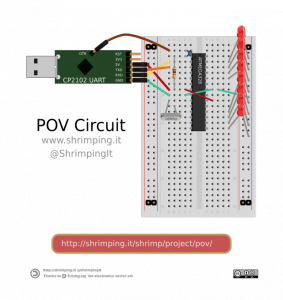
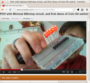
It is instructive to compare @Adafruit‘s very popular MiniPOV3 “Persistence of Vision” PCB kit and the POV project we constructed for workshops with @MadlabUK and @ideasfoundation.
Adafruit offer fantastic resources of all kinds, (not just PCBs), and we’re big fans of their work. However, in this case, we’re disappointed that for $17.50 you get a text-display circuit which is…
- Not programmable, without specialist skills and equipment – for example if you want to change the font or display icons or author other behaviour with the LEDs.
- Requires a specialist piece of hardware, not supplied within the kit cost, to change the text which is displayed
- Hard to re-purpose, for example if you want to add an extra hardware feature, (though a tilt-switch may possibly have been anticipated as a stealth feature, based on a pair of curious looking unused pads).
- Is easily programmable, and includes the source code
- Includes a USB adaptor to re-program the device in any way using your laptop, free drivers and Arduino software.
- Provides examples of specialising the behaviour, for example by selecting different fonts, or designing icons
- The components and circuit can be easily repurposed or redesigned; adding tilt sensors or anything else is trivial using the additional space on the 400-tie-point breadboard
Participants in our workshops, incidentally, go home with a fully-fledged #Shrimp kit meaning they can use it as a substitute Arduino Uno for a whole world of projects. It’s not just a POV – you can take it anywhere you want from here.
Learning Objectives of soldering a PCB?
When I see soldering workshops where the public are invited to make kits at various events, I can’t help being reminded of the hundreds of thousands or millions of people around the world, for whom putting components onto PCB is their hand-to-mouth day job, leaving little time for leisure and no means of expressing their creativity. That’s sweatshops, not workshops.
The key thing is, what are you learning, and in what way are you being empowered, by putting together a MiniPOV3?
We can do better. If we’re preparing learners to drive forward UK PLC, then we don’t want to go back in time to a manufacturing economy, but forward to a creative economy.
In particular, we can design for comprehension and expression.
First, comprehension. A manufactured PCB is often near-impossible to trace if you’re interested to know exactly how it works. Breadboard and stripboard on the other hand, can be trivially traced. The connectivity of each component is clear, and can be introduced along with its function in the circuit, rather than simply inserted with no explanation.
Second, expression. If you prototype something on breadboard and transfer it to stripboard, even if you’re following our guidance and instructions to do so, you should be intimately aware that you have the freedom to break away from our choices at any moment. If you want 10 LEDs instead of 8, then go for it. If you don’t want a POV, and prefer an electronic dice, then do that – you’re in a generic microcontroller-prototyping environment. If you want a tilt-switch so it paints both backwards and forwards, this is a relatively trivial, but very rewarding, modification where…
- …you don’t have to wait for someone else to have the idea
- …you don’t have to wait for them to design it on Eagle
- …you don’t have to wait for them to send it to a far-east factory to layer a PCB incorporating the new feature and send it on to you.
- …you just build it!
ShrimPCB
It’s certainly feasible to put the #Shrimp onto a PCB very cheaply, but it’s hard to know what exactly the benefit would be.
To create a project, you’d need to wire additional components to your microcontroller board in any case, and a breadboard is a decent way to achieve this. In practice, our circuit takes just a few minutes to build on breadboard, especially with laser-cut printed overlays, and requires very little work to prototype on stripboard either (just one line of spot cuts beneath the chip).
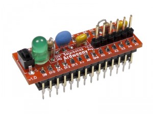
Most of the heavy lifting is done by the ATMEGA anyway, and it’s a shame to introduce another pinmapping into the world for people to get their heads around. So far, the most inspiring and practical PCB design we’ve seen for prototyping use is the @Solarbotics Ardweeny which literally piggybacks on the ATMEGA, but simplifies attaching the key protective components to the chip, adding a diagnostic LED and figuring out which pins need to be attached to the UART. Hopefully you can do this on a friction-fit without soldering it in place. It’s on the Xmas list.
Better still, a project prototyped with the Ardweeny is pin-compatible with the #Shrimp and other projects based on raw ATMEGA pinouts. Shame it’s not just a bit cheaper, especially in volume, but as an open design you can always fabricate your own.
PCBs as Advanced Prototyping Tools
We know that many people have developed the skills to design and deploy single-layer PCBs using workshop materials, or are confident enough of their designs to get multi-layer PCBs fabbed and shipped from cheap small-volume suppliers, and therefore consider them to be a prototyping approach.
However, this is not for the faint hearted. To begin with, the tools commonly used to design a PCB layout, especially a multi-layer design, are commercial, specialist software, with rare exceptions. The design process is unforgiving of error. Although rework is often possible to patch a mistaken board design – cutting tracks and soldering extra jumpers – even diagnosing the problem takes a significant mental balancing act.
It’s really hard for us to see an accessible route for learners to work with PCB as a prototyping tool compared to the simplicity of solderless breadboard. If you disagree, why not put together an idiot-proof, step-by-step guide which can help learners and teachers to use it for their projects instead of breadboard. If you agree it’s a bit advanced, then perhaps you’ll agree with our choice to lead by example by building the #Shrimp itself on breadboard.
Not Dissuaded?
If you DO make a ShrimPCB, then let us know how you got on, and we’ll make sure you get prominent links from this site.
Not everyone will agree with our perspective and we want to accommodate a whole diversity of activities around Shrimping. However, at this stage, given the emphasis of our work, PCBs just aren’t our bag.
Looking forward to the comments below.
Update1: I’m pleased to say that iMartyn has altogether ignored our (rather narrow-minded) perspective outlined below, and gone ahead and created a ShrimPCB anyway! Above, we present an argument that providing PCBs to learners isn’t a useful thing, but read to this comment thread to see why what Martyn has done has a special kind of value – not just providing PCBs, but providing the means of making your own.
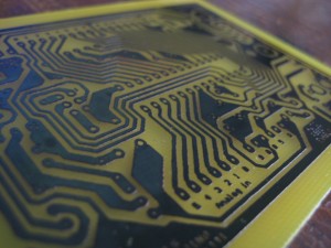
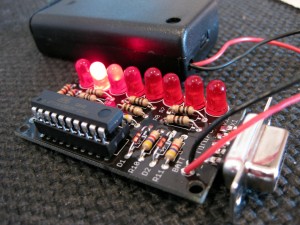
Many of his hacks, including the first versions of the TV-B-Gone, were built using the MiniPOV3 kit by hardware hacker Ladyada. That kit lets you create ghostly messages with a bank of 8 blinking LEDs, by waving the LEDs back and forth in the air.
By making changes to the kit’s circuitry, replacing the red LEDs with different colors and reprogramming the included microcontroller, Altman has made not only the TV-B-Gone, but also glowing lights that respond to hand gestures, an electronic “dog” that spins its tail in reaction to sunlight, a 3x3x3 cube of LEDs that displays abstract 3-dimensional patterns, and even a pair of glasses with embedded, flashing LEDs and a pair of headphones for getting your brain waves into a meditative state.



I respect your view, but I think there are (at least) two groups of potential Shrimp users with differing concerns.
Some are confident enough that they will breadboard a Shrimp, make a stripboard version, and then use their new-found knowledge to create lots of projects from scratch.
Others will be more cautious. They will need a quick win before they develop the confidence to branch out. For them a PCB Shrimp kit could be attractive, and be a stepping stone on to more independent experiments. Of course, a workshop could help them through the first stages of Shrimping but that is not an option available to everyone.
I think you’ve got a point about learners out there, who don’t get a chance to workshop with us, needing something to build their confidence.
We’ve finally started distributing kits based on the prototyping materials and approaches we recommend and hoping people can get their early successes that way. Early days and the support information is continually iterating, but getting some positive feedback so far. See the new ‘Kits’ tab at http://shrimping.it
I definitely agree with your perspective on acknowledging the spectrum of learners and experimenters out there.
I think you’re emphasising one of the beneficial aspects of a (screen-printed) PCB build; that the positions of the components are self-explanatory. However, there are many not-so-accessible aspects of a PCB build. Actually having to solder components has to be number 1.
I believe we can replicate the benefits of self-explanatory positioning on solderless breadboard using paper overlays (inspired by Oomlout’s ARDX kit).
We’ve tested this out a few times with our POV experiment, (see http://shrimping.it/blog/persistence-of-vision/ ) and so far, so good. Only one of the students we worked with is pictured, but there were 45 in the class, and many even succeeded at designing their own icons, given the accelerated build time from the paper overlays! http://madlab.org.uk/content/tag/minipov/
Better still, people can follow this guidance and their circuit will work instantly, without any soldering step – an even quicker win!
Another aspect of a typical PCB build is that it’s typically an applied project, “for something”, rather than just a generic Microcontroller hobby board to which you’re expected to add your own ideas and prototyping comprehension (which would be a big ask for some early learners, I agree). I believe our focus on deployed projects like the POV, Webserver, Robot, means that Shrimpers get this benefit too.
Did I understand you correctly? What other aspects of a PCB build should we be aware of, beyond physical robustness of course?
Okay, here’s my view on this, as a member of a local hackspace.
shrimping.it is an awesome project and inspired me to spend about the same money as an Arduino to buy enough components from Farnell to make 10 shrimps. Still have a few left as well, to ensure that the hackspace always has a kit available for newcomers.
The reason I made my ShrimPCB board was actually to learn the process of making PCBs myself. Sure breadboards are great but can be a bit unreliable – I like to carry a shrimp round with my in my bag to play with and show others but after about a month of jiggling it gets very sensitive to knocks and bumps. There’s also the fact that some chips just are that much cheaper in soic, qfp or ssop form factors or don’t exist at all in dip.
The 328 itself is made in such quantities of dip package that it is very cheap and easily available, but for instance, dual-mode bluetooth 4.0/2.0 chips only actually exist in horrible formats.
I think learning PCB layout is a great skill to have and yes, it’s more advanced and playing with chemicals is also not the safest hobby, but being able to make breakout boards such as some of the dangerousprototypes boards (e.g. http://www.seeedstudio.com/depot/xqfp-breakout-board-08mm-p-757.html?cPath=175_177) is great.
Also, soldering is actually fun and a lot easier than people think – usually people who think they can’t solder have been using a crappy iron and trying to salvage parts from a pre-made board, so think it’s really hard. I love showing people how to solder, and at emfcamp ended up running some of the soldering workshops.
So the ShrimPCB as far as I’m concerned is just another tool to learn with – I certainly learned how poor the options are regarding designing them in Free software, how you need to flip the transparencies and how the sponge-acid trick takes too long for my limited patience. I’ve put it up on github so that people can take a simple circuit – i.e. the shrimp with an led on pin 13 – and try their hand at manufacturing their own without having to learn how to use the design software. There’s even PDFs and SVGs so you can simply print it out and begin.
It also I guess is useful in that it is embedable into say a robot with a little solder and then when the robot bumps into the wall the related jiggle doesn’t knock the wires out.
Not too proud to say this development proves us wrong that we didn’t need to think about PCBs. Really glad you went ahead with it.
To my mind, what you’ve achieved is create another possible forward direction for people who start with a @ShrimpingIt circuit on solderless breadboard, and want to take it somewhere.
Sharing the source is really fundamental as it gives people a head start for when they want to specialise the circuit for their own application, and the fact you can use this example to talk through the process and share some of the gotchas is also critical.
It’s worth noting, maybe in the material that you prepare, that a lot of the benefits (robustness etc) can be achieved through components soldered on copper stripboard, but there’s plenty of things which can’t – just as you mention in your comment (unusually sized components which require you to buy yet another Sparkfun breakout, or maybe just being near-impossible to solder without a proper footprint).
Still of the view that _providing_ a PCB to someone isn’t all that useful, but providing the _means_ of producing their own PCB is a totally different story. Hats off to you, sir.