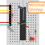
Note, there is no longer a diode in the preferred schematic. It was only there to handle the rare case of a spurious high-voltage reset signal, but more often than not, was wired backwards, preventing the Shrimp from running. The pragmatic decision was to remove it.
[…] basic schematic of what my board looks like; I've omitted all the wiring that's due to the basic Shrimp schematic, which my board is based off; this is my first computer-made schematic, so go don't be too harsh on […]
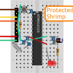
Thanks to the diligent Dominic Theaker, we were alerted to an error lying in the schematic all this time (probably masked by the fact people refer to the graphical layout instead when building).
The TXD pin on the CP2102 should actually connect to PD0 (Arduino Digital Pin 0 described as RX) and the RXD pin on the CP2102 should actually connect to PD1 (Arduino Digital Pin 1 described as TX). See http://arduino.cc/en/Hacking/PinMapping for which is which.
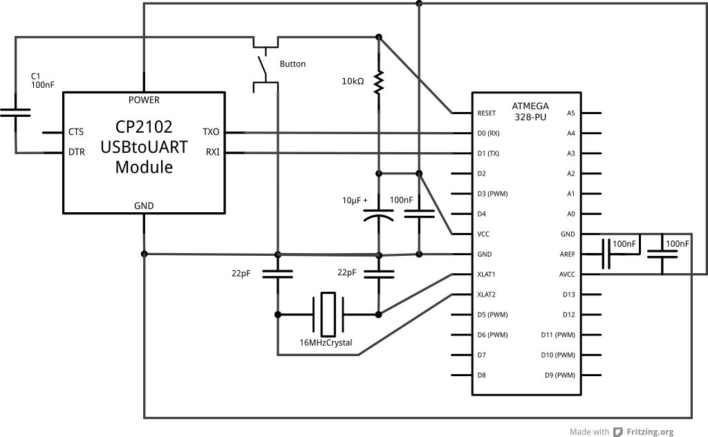


Note, there is no longer a diode in the preferred schematic. It was only there to handle the rare case of a spurious high-voltage reset signal, but more often than not, was wired backwards, preventing the Shrimp from running. The pragmatic decision was to remove it.
[…] basic schematic of what my board looks like; I've omitted all the wiring that's due to the basic Shrimp schematic, which my board is based off; this is my first computer-made schematic, so go don't be too harsh on […]
Thanks to the diligent Dominic Theaker, we were alerted to an error lying in the schematic all this time (probably masked by the fact people refer to the graphical layout instead when building).
The TXD pin on the CP2102 should actually connect to PD0 (Arduino Digital Pin 0 described as RX) and the RXD pin on the CP2102 should actually connect to PD1 (Arduino Digital Pin 1 described as TX). See http://arduino.cc/en/Hacking/PinMapping for which is which.